
Measurable metrics to curtail fouling & premature equipment failure
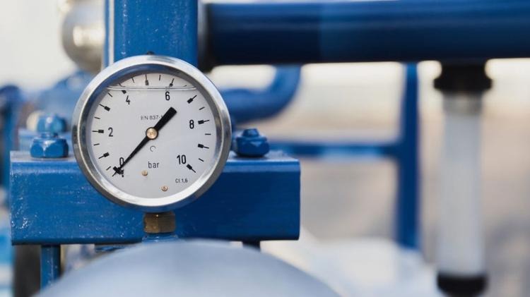
During the journey of fluid inside the heat exchanger, high-velocity results in a pressure drop. The maximum allowable Delta P is defined by the process requirement and available pumping capacity. About 10% accumulation is used up in this process. About 20% is reserved to tackle variations in the process. When it is too high, the flow rate is reduced. While a small amount of pressure drop is essential for fluid movement, a larger one impacts operations. It may even cause higher operational cost and too much Delta P can result in equipment failure which is undesirable and affects the investment.
- What exactly is the correlation between pressure drop and the actual performance of a heat exchanger?
- How is the pressure drop reduced for optimal performance of Heat Exchanger?
- Is the flow rate also affected by a higher pressure drop?
- Why curtailing fouling is equally significant to pressure drop?
These are some noteworthy and major questions an experienced Heat Exchanger designer needs to tackle while calculating and preparing an optimal product for clients.
Considering the importance of pressure drop for shell and tube designs, our experts throw light on these queries. The designer can prepare measurable metrics to curtail fouling: one of the critical factors affecting the Heat Exchanger application. The design should be so watertight that during normal conditions, there is no problem in the operational journey. And, the equipment remains a long-term investment for a plant.
What we will understand from this blog:
- How does pressure drop affect heat exchangers?
- Prevention of failure due to pressure drop in process design of Heat Exchangers
- Thermal Design Fundamentals of Shell and Tube Heat Exchanger
Please Note: We shall also answer the questions raised above to gain clarity while opting for a reasonable and suitable Heat Exchanger.
Pressure drop formulations terminology for reference:
The pressure drop on circular pipe is calculated by Darcy Weisbach equation,
ΔP=f (L/D)( ρV²) = ρghl, where
ΔP = Pressure Loss, N/m²
hl = frictional head loss, m
L = pipe length, m
D = pipe diameter, m
V = average flow velocity of fluid (= Q/A), m/s
g = acceleration due to gravity = 9.81 m/s²
f = friction factor, a dimensionless empirical factor that is a function of Reynolds Number (Re = DVρ/μ), where
ρ = fluid density, kg/m³
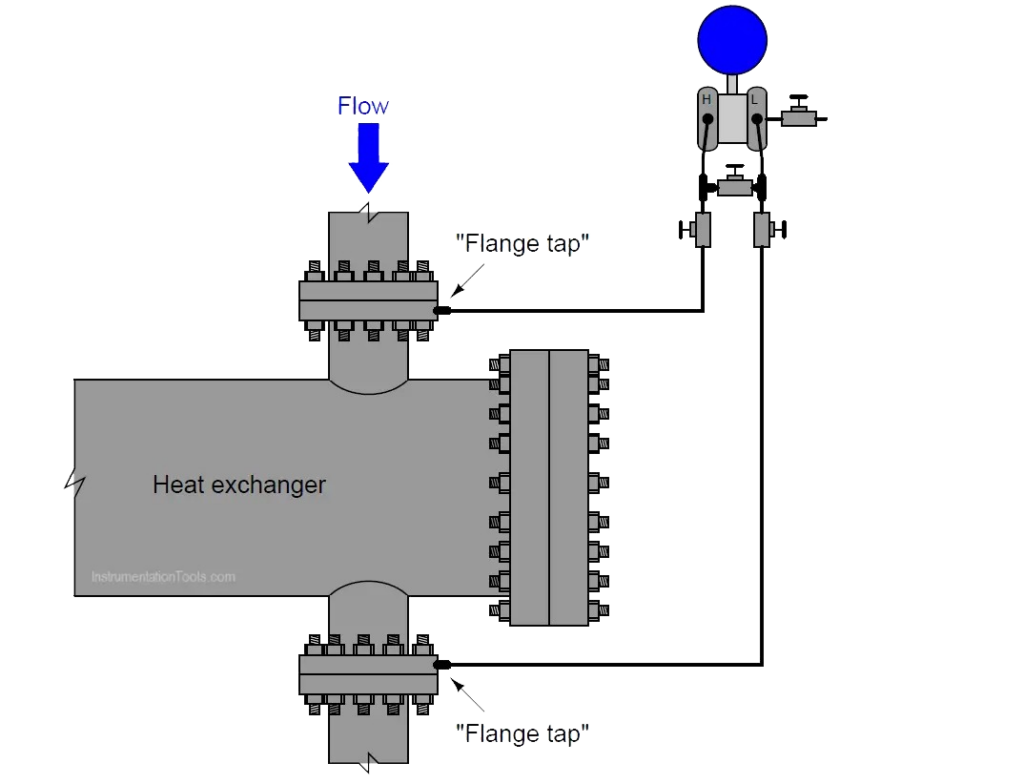
How does pressure drop affect heat exchangers?
A pressure drop is recognized as an alteration in total pressure between two points in a fluid-carrying device/equipment. The fluid enters one end of the heat exchanger and leaves the other one. During this process, a pressure drop is created. This normally happens when there are restrictions or blockages to the flow. When the velocity is low, the pressure drop also reduces. And in the case of higher velocities, the pressure drop increases.
Hence the pressure drop is related to the velocity and velocity is an important parameter to decide on heat transfer coefficients in the exchanger. Higher the velocity, higher will be the heat transfer coefficient and ultimately will result in higher pressure drop.
The optimum design is one which offers lowest possible pressure loss with highest heat transfer coefficient. Hence as a designer most important is to select the right construction of the exchanger.
This is the reason why a designer has to find ways to optimize the pressure drop across the exchanger
Correlated to this is the performance of the HE which a designer has to control. It is a significant perimeter that has to be factored. Erosion issues, limiting flow rates, and velocity contribute to efficiencies. Due to the high flow the pressure gradient results in turbulence, required for thermal transfer. It also may increase the pumping charges. A compromise has to be made to ensure the performance of the HE does not suffer.
As a Shell & Tube Heat exchanger is not just a circular pipe, to calculate the pressure drop across tube and shell sides respectively, following numerical equations are followed,
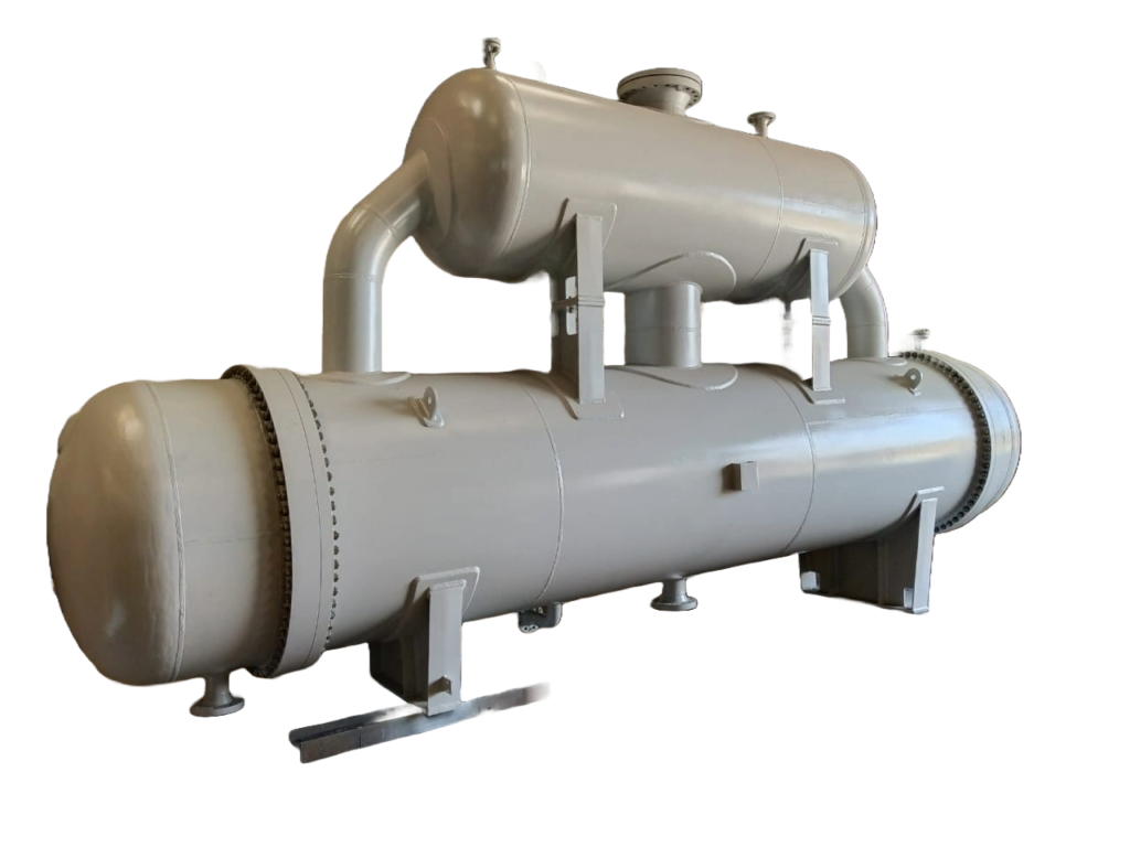
Shell and tube heat exchanger
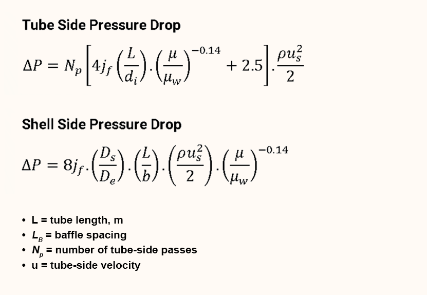
jf= friction factor
ut= tube velocity m/s
us= shell velocity m/s
Ds= diameter of shell (m)
de= equivalent diameter of shell
Delta Ps= shell side pressure loss
Delta Pl= Tube side pressure loss
How to optimize pressure drop in process design of Heat Exchangers
When we design the Shell and Tube for our clients, the team tries to manage and limit the pressure drop. They prepare a configuration suitable for the plant operations onsite.
This section will also address the question on the optimal performance of the fluid inside the HE.
To reduce the Pressure Drop on the shell side the following ways are applicable:
- Baffle Selection: The purpose of providing baffles in the exchanger is to create more turbulence and to support the tube bundle. The turbulence created due to baffles leads to higher pressure drop, hence the right choice of baffle is important. E.g. When there is a liquid in the shell, based on pressure drop perspective, following are the baffle choices,
- Segmented Baffle (Single) – offers high turbulence, high pressure drop and is easy to manufacture.
- Double Segmented – offers moderate turbulence, moderate pressure drop and is a little difficult to manufacture.
- Rod Baffle – offers low turbulence, low pressure drop and is difficult to manufacture.
- No tube in window – offers no turbulence, no pressure drop, provided just for support.
- Baffling space increases the cross-flow. As the area is large, the pressure drop is limited to the minimum. Higher the baffle spacing, lower the turbulence and pressure drop.
- By increasing the baffle cut, the window flow area is enlarged. The limitation does not exceed 45% of the diameter inside the shell.
Apart from the baffles the shell side pressure drop depends on the following factors,
- Tube pitch and pattern: Pitch is the center to center distance between two adjacent tubes. Higher the pitch, lower will be the pressure drop and turbulence. A triangular pitch offers higher pressure drop and turbulence. Square pitch offers lower pressure drop and turbulence. Designer has to select the right pitch and pattern.
- The shell diameter is increased, and the tube length is cut. This may affect the transfer coefficient which leads to lower pressure drop in the shell.
- Nozzle Size: Proper nozzle size selection is important to ensure less pressure loss. For liquid, velocity in the nozzle should be equal to avg. velocity in shell or equal to the liquid line size. It is similar in case of gases. Important factor is ρV² which needs to be as low as possible.
To reduce the Pressure Drop on the tube side the following ways are applicable:
- Tube Velocity: Higher the velocity, higher is the pressure drop.
- of Passes: Higher the no. of passes, higher is the pressure drop.
- Nozzle Sizes: Proper nozzle size selection is important to ensure less pressure loss. For liquid, velocity in the nozzle should be equal to avg. velocity in the tubes or equal to the liquid line size (provided line size is selected properly). It is similar in case of gasses. Important factor is ρV² which needs to be as low as possible.
Thermal Design Fundamentals of Shell and Tube Heat Exchangers
As we return to the drawing board, the thermal performance is integral to any shell and tube design. With customized plans, we take into account the surface area, and calculate the hydraulic analysis to determine the pressure drop of flowing fluids. The important factors include pumping power to keep the flow smooth.
The points that matter for a successful design are dependent on the following principles.
- Heat exchangers need proper allowable pressure drop in the presence of fouling. It should be operational until the next maintenance period of the heat exchanger without reduction in the process stream flow.
- The design of the equipment should bear the service conditions prevalent in the plant environment.
- The configuration of the exchanger should be such that any part can be replaced which undergoes erosion, cleaning, or replacement. It should be strong enough to resist vibrations or aging after long usage.
- It is up to the designer to make provision for flexible piping and valves with a multiple and advantageous arrangement.
- One unit can be isolated for maintenance without disturbing the other parts and the located plant.
- The entire equipment should be cost-effective for the client considering the requirements.
- If there are limitations of the plant, the configuration should be created to suit the lifting and servicing capabilities.
Further, the focus is on the following queries related to the design and its impact on operations.
Is the flow rate also affected by a higher pressure drop?
Yes, higher pressure loss means higher head required for pump and if pump is not designed for higher head, it will result in reduction in flow rate.
Why curtailing fouling is equally significant to pressure drop?
Fouling means deposition and accumulation of unwanted materials such as scale, insoluble salts, algae, solids etc, on the heat transfer surface At no stage, fouling is desirable in any heat exchanger.
It gets deposited in the shell/tube side and is also prone to leakages. Fouling also leads to higher corrosion and premature failure of the equipment. Because of fouling, pressure drop across the heat exchanger increases significantly and reduces thermal performance of the exchanger. So for a long lasting life of the heat exchanger, regular cleaning of the deposition should be done. There are many other reasons for fouling and that needs to be considered depending on the industrial usage and application.
Conclusion
In the selection and design of Heat Exchanger, pressure drop plays a vital role. Pressure drop also affects the operational cost and capital investment. Lower pressure drop means lower operational cost and higher capital investment. Vice-Versa.
At Kinam Engineering, our highly qualified heat transfer engineers have an aim to fulfill client’s requirements along with best balance on operational efficiencies, operational cost and capital investment. In case you need more information do contact our heat transfer experts to take your project forward.